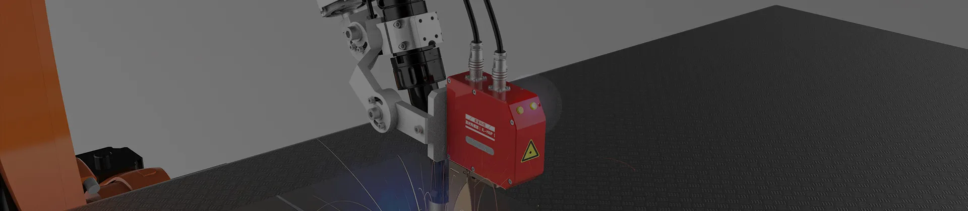




When I evaluate an automated welding cell, I do not begin with the robot alone. I first examine how the system detects the joint, measures process conditions, corrects the toolpath, and records quality data. Understanding Automated Welding Sensors is essential because these devices connect physical weld conditions with robot control, helping manufacturers address seam variation, part-positioning errors, thermal distortion, and inconsistent process results.
Automated welding sensors are measurement devices used before, during, or after welding. Depending on the application, they may detect a joint through optical patterns, laser profiles, electrical arc behavior, contact signals, force, temperature, or ultrasonic response. The correct sensor is determined by the welding problem, not by the sensor category alone.
!
Automated welding sensors measure the position, geometry, temperature, force, electrical behavior, or internal condition of a workpiece and send that information to a robot controller, PLC, welding power source, or inspection system. The controller then uses the measurement to locate the joint, adjust the torch path, modify process parameters, or reject a defective part.
In practical terms, a sensor can perform four main jobs:
A sensor does not automatically improve a weld simply because it has been installed. The measurement must have a defined accuracy, update rate, response time, measurement range, environmental protection level, and communication method that match the production process.
Most sensor-enabled welding systems follow a closed-loop sequence. First, the sensor detects a joint, edge, arc condition, temperature change, or force response. Next, signal-processing software filters interference and converts the measurement into coordinates or process values.
The controller compares the measured condition with the programmed target. If the joint has moved 1.5 mm to the left, for example, the robot may shift the torch path by a corresponding amount, subject to the system’s correction limits and response time. After welding, the system can compare inspection data with acceptance criteria and save the result against the part number, weld location, and production time.
A complete workflow typically includes these stages:
This closed-loop structure is more useful than simply adding a sensor to a robot. It defines what happens when the sensor sees a deviation and prevents measurement data from becoming an unused display.
The following comparison shows the primary sensor types and their most suitable applications.
| Sensor type | Main measurement | Typical application | Key limitation |
|---|---|---|---|
| Laser vision sensor | Joint profile, seam center, gap, edge position | Robotic welding and seam tracking | Smoke, reflections, spatter, and lens contamination |
| Optical or camera sensor | Visual position and surface features | Part positioning and surface inspection | Requires controlled lighting and clear visibility |
| Arc sensor | Electrical changes caused by joint position | Through-arc seam tracking in MIG, MAG, or similar processes | Depends on stable arc behavior and suitable weaving |
| Touch sensor | Contact between torch electrode and workpiece | Joint finding and part positioning | Adds contact time and may mark sensitive surfaces |
| Proximity sensor | Distance or presence of a component | Workpiece detection and fixture confirmation | Limited geometric information |
| Force/torque sensor | Contact force and resistance | Assembly, contact detection, and controlled interaction | Requires mechanical protection and calibration |
| Temperature sensor | Surface or weld-zone temperature | Preheating, interpass monitoring, and thermal control | Emissivity and surface condition affect readings |
| Ultrasonic sensor | Internal discontinuities and bond condition | Post-weld inspection | Often requires coupling, scanning, or separate inspection equipment |
Laser seam tracking projects a laser line or pattern onto the workpiece and captures the reflected profile with a camera. Software then calculates the weld groove, edge alignment, height difference, or seam center. This approach can provide non-contact measurement before and during welding.
Laser vision is useful when the joint is visible and the workpiece has meaningful geometric features. It is especially suitable for sheet metal, pressure vessels, structural steel, pipelines, aluminum assemblies, and components affected by thermal deformation.
Optical systems must be evaluated against reflective surfaces, dark coatings, arc brightness, smoke, and spatter. A supplier should provide practical information about measurement range, minimum detectable gap, frame or update rate, operating distance, and protection against dust or water. A nominal accuracy figure without the corresponding working distance and test conditions is insufficient for system selection.
Arc sensors infer joint position from changes in welding current or voltage while the torch moves through a controlled weave pattern. If one side of the joint produces a different electrical response from the other, the controller can estimate whether the torch is centered.
Arc sensing is useful for repetitive production with stable joint geometry and compatible welding processes. It does not require a separate optical device in the same way as laser tracking, which can reduce equipment around the torch.
However, arc sensing is affected by wire extension, arc length, welding current, travel speed, weave pattern, joint gap, and surface condition. It is less suitable when the seam is difficult to access, the joint changes abruptly, or the process cannot maintain a stable arc long enough to produce a reliable signal.
Touch sensing uses electrical contact between the torch electrode or a dedicated probe and the workpiece. The robot moves through a search routine until contact is detected, then records the position. This method is commonly used to locate part edges, identify fixture variation, or establish a starting point before welding.
Proximity sensors detect whether a part or fixture is present within a defined distance. They are useful for interlocks and position confirmation but generally do not provide the detailed seam geometry required for tracking.
Force and torque sensors measure mechanical interaction between the robot tool and the workpiece. They can identify contact, fixture interference, clamping problems, or assembly resistance. Their output is valuable in specialized cells, but the sensor must be protected from impact, vibration, heat, and excessive welding spatter.
Temperature sensors support weld process monitoring by measuring preheat temperature, interpass temperature, or surface cooling behavior. Infrared systems are non-contact, while thermocouples provide localized measurements when they can be installed consistently.
Ultrasonic welding inspection sensors examine internal conditions that surface vision may not detect. They can identify indications related to lack of fusion, inclusions, cracks, or porosity, depending on the method, calibration, material, probe, and inspection procedure.
These technologies are often used after welding rather than for real-time torch correction. They should be treated as part of a wider quality-control plan, not as replacements for correct joint preparation, welding procedure qualification, and operator or engineer review.
I recommend selecting robotic welding sensors by identifying the source of variation first. A system that solves fixture misalignment may not solve thermal distortion, and a sensor that detects seam position may not verify internal weld integrity.
| Production problem | Appropriate technology | Why it fits |
|---|---|---|
| Part position changes between cycles | Touch sensing, optical sensing, or proximity detection | Establishes the actual starting location |
| Joint moves because of heat distortion | Laser seam tracking or arc sensing | Corrects the path during welding |
| Zero-gap or narrow-gap joint | High-resolution laser vision | Detects small geometric changes |
| Long structural weld with stable geometry | Arc sensor or laser tracking | Supports continuous correction |
| Strongly reflective aluminum surface | Laser system with reflection-control algorithms or controlled optical setup | Reduces false readings caused by reflected light |
| Need for preheat or interpass control | Temperature sensor | Confirms thermal limits before the next pass |
| Suspected internal defects | Ultrasonic inspection sensor | Examines conditions below the surface |
| Fixture presence or clamp confirmation | Proximity sensor | Prevents the robot from running on an incomplete setup |
| Tool contact or collision risk | Force/torque sensor | Detects abnormal mechanical resistance |
Intelligent-Laser, associated with Tangshan Yinglai Technology, focuses on laser vision systems for robotic welding and specialized automated machines. Its product range includes zero-gap seam tracking, sheet-metal seam tracking, medium- and heavy-plate tracking, wide-field-of-view sensing, general seam tracking, and laser sensors for special welding machines.
The company states that it was founded in 2013 and provides research, production, process testing, system integration, technical consultation, and related support. Its applications include new-energy equipment, pipe and pressure vessels, automotive parts, power equipment, engineering machinery, aerospace, steel structures, and corrugated plates.
Laser seam tracking and arc sensing are not interchangeable. Laser systems measure joint geometry directly, while arc sensors infer joint position from electrical behavior during welding.
| Evaluation factor | Laser seam tracking | Arc sensing |
|---|---|---|
| Measurement timing | Before and during welding | Primarily during welding |
| Physical principle | Optical profile measurement | Current or voltage response |
| Need for torch weaving | Usually no, depending on system | Commonly required |
| Performance on visible geometric seams | Strong | Moderate to strong |
| Sensitivity to smoke and spatter | Requires filtering and protection | Less affected optically |
| Sensitivity to arc stability | Low to moderate | High |
| Installation complexity | Sensor mounting and calibration | Welding-process setup and controller integration |
| Best use case | Variable joint geometry and thermal movement | Repetitive joints with stable arc conditions |
For a narrow gap, irregular tack welds, variable edge alignment, or significant workpiece distortion, I generally consider laser vision first. For a stable heavy-plate process with predictable weaving and limited optical visibility, through-arc seam tracking may provide sufficient correction with a simpler optical arrangement.
The primary quality benefit is reduced dependence on the assumption that every part is positioned exactly like the previous part. A sensor measures the actual condition and allows the robot to correct a defined range of variation.
The productivity benefit depends on the baseline process. If manual operators spend 20 minutes per batch locating joints, a pre-weld sensing routine may reduce that activity. If a defective weld costs 30 minutes of grinding and repair, reducing the defect rate by even 2 percentage points can produce a measurable return, provided the sensor does not add excessive cycle time.
I recommend tracking these metrics before and after installation:
Automated welding sensors are often worth the investment when joint variation directly causes rework, when production volume is high, or when manual inspection cannot provide timely feedback. They may not provide sufficient return when the fixture already holds the joint within a narrow tolerance, production volume is low, or the sensing system requires more maintenance than the process can support.
Smoke can reduce optical contrast, while spatter can block a lens or alter the measured profile. Reflections from aluminum, stainless steel, polished surfaces, or coatings can create false edges. Thermal distortion may also change the joint shape faster than the correction algorithm can respond.
Fixture variation creates another challenge. If the workpiece shifts beyond the sensor’s measurement range, the system may produce an alarm rather than a useful correction. Calibration drift can result from mechanical impact, bracket movement, temperature changes, or contamination.
I recommend defining maintenance requirements before purchase. The specification should state cleaning frequency, calibration procedure, replacement parts, protection rating, operating temperature, cable routing requirements, and expected response to sensor failure. The robot should have a safe fallback condition, such as stopping the cycle, switching to a verified reference path, or sending the part to manual inspection.
I use the following decision process when comparing automated welding sensor systems.
Measure the joint movement, gap range, edge offset, part rotation, thermal distortion, and fixture repeatability. Record at least 30 to 50 representative parts if the process allows it. Without baseline data, the required measurement range and accuracy are difficult to select.
Choose laser vision when direct geometric information is required. Choose arc sensing when the weld process is stable and electrical feedback can reveal the joint position. Choose touch sensing for discrete part finding, proximity sensing for presence checks, and ultrasonic inspection for internal quality evaluation.
Review measurement accuracy, working distance, field of view, update rate, response time, correction frequency, operating temperature, protection rating, and communication protocol. For example, a sensor with a 100 Hz update rate may be suitable for one travel speed but insufficient for another if the robot moves too far between measurements.
Do not test only clean steel under ideal lighting. Include smoke, spatter, tack welds, reflections, thermal distortion, joint gaps, surface coatings, and expected fixture variation. Record missed detections, false positives, correction delays, and maintenance actions.
Include the sensor, mounting hardware, controller interface, software, robot programming, commissioning, calibration tools, spare parts, training, cleaning, downtime, and annual service. Compare these costs with reduced repair hours, lower scrap, improved inspection coverage, and increased production availability.
I recommend starting with one representative weld rather than installing sensors across an entire production line. Select a joint that has measurable variation, a meaningful repair cost, and enough production volume to generate comparison data.
Before commissioning, define the coordinate frame, sensor mounting angle, tool center point, scan distance, correction limits, alarm thresholds, and data-recording method. The robot program should distinguish between a small correction, a recoverable measurement error, and a condition that requires the part to be stopped.
Operators and welding engineers should also receive practical instructions for cleaning, calibration checks, alarm review, and manual override procedures. A sensor system should not become dependent on one programmer who understands its configuration. The cell documentation should include wiring, communication settings, calibration records, software versions, and acceptance-test results.
Understanding Automated Welding Sensors requires more than comparing product categories. I need to match the sensing principle to the production problem, then verify accuracy, update rate, response time, operating range, environmental protection, integration effort, and total cost of ownership.
Laser seam tracking is generally suited to visible joint variation, narrow gaps, and thermal distortion. Arc sensors can support stable, repetitive welds during the process, while touch, proximity, force, temperature, and ultrasonic sensors address positioning, safety, thermal control, and inspection requirements.
For manufacturers evaluating automated welding sensors in 2026, the next practical step is to document 30 to 50 representative parts, quantify current repair and positioning variation, and run a controlled sensor trial under real welding conditions. Yinglai and Intelligent-Laser illustrate the type of supplier capable of combining laser vision hardware with process testing, system integration, and robotic welding applications, but the final decision should be based on measured performance in the intended cell rather than on sensor type alone.
Latest Blogs
12
Oct. 2026
Understanding Automated Welding Sensors
When I evaluate an automated welding cell, I do not begin with the robot alone. I first examine how the system detects the joint, measures process conditions, corrects the toolpath, and records quality data. Understanding Automated Welding Sensors is essential because these devices connect physical weld conditions with robot control, helping manufacturers address seam variation, part-positioning

23
Sep. 2026
Laser Vision Seam Tracking Sensor: Features and Advantages
A Laser Vision Seam Tracking Sensor projects a laser line or uses optical imaging to detect the actual weld-joint position, then sends correction data to a robot, PLC, or welding head. I use this technology when programmed robot paths cannot compensate for fixture tolerance, part distortion, or changing seam geometry.

12
Aug. 2026
Choosing the Right Seam Tracking Sensor for Your Production Line
Choosing the right seam tracking sensor is essential for modern production lines. Many manufacturers face challenges with inconsistent seams, which can lead to defects in products. Seam tracking sensors help in maintaining alignment during the manufacturing process. These sensors play a crucial role in improving quality and reducing waste.
Let Us Provide a Professional Solution for You Today
Our experienced team can provide customized service to all kinds of projects. Also, we provide 24/7 aftersale service.
Our aim is to make sure all customer can use the laser sensor after receiving it instead of put it in the box.