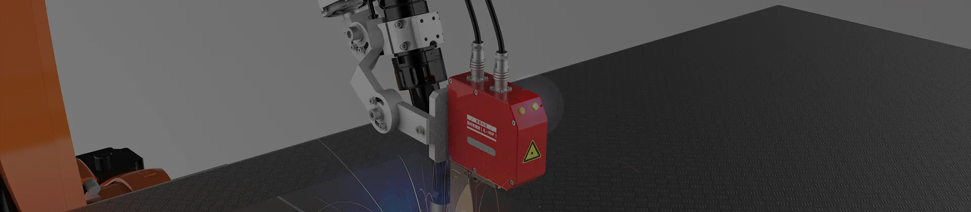




A Laser Vision Seam Tracking Sensor projects a laser line or uses optical imaging to detect the actual weld-joint position, then sends correction data to a robot, PLC, or welding head. I use this technology when programmed robot paths cannot compensate for fixture tolerance, part distortion, or changing seam geometry.
!
A laser vision seam tracking sensor is an optical weld-joint detection device used to measure the position and geometry of a seam before or during welding. The sensor projects a structured laser line across the joint, captures the reflected profile with a camera, and calculates the deviation between the programmed path and the actual joint. A controller then converts that deviation into motion commands for the robot or welding actuator.
The complete signal chain normally includes laser projection, image capture, profile extraction, seam-feature recognition, coordinate transformation, and robot correction. This sequence allows the system to identify joint centerlines, edges, grooves, fillets, or other geometric features without physical contact with the workpiece.
I distinguish seam finding from seam tracking. Seam finding usually measures the joint before welding to establish an initial path, while seam tracking continues to monitor the joint during movement and corrects the torch position as conditions change.
The sensor is generally mounted ahead of the welding torch, although the exact position depends on torch angle, joint accessibility, welding direction, and the required look-ahead distance. As the robot moves, the laser crosses the joint and the camera captures the reflected line. Software then filters the image and identifies geometric features that represent the weld seam.
The controller compares the detected seam position with the reference position stored during teaching or calibration. If the seam has shifted horizontally, vertically, or in some cases along multiple axes, the controller calculates a correction value. The robot then adjusts the torch path while maintaining the programmed welding speed, orientation, and process parameters.
A typical operating sequence is:
The quality of this process depends on more than the camera or laser diode. Sensor resolution, optical alignment, signal-processing delay, robot communication, mounting rigidity, and the selected tracking algorithm all affect the final correction result.
When I compare a laser seam tracking sensor, I do not rely on the product name alone. I review the measurable operating range and how each specification fits the welding process.
| Specification | Why It Matters |
|---|---|
| Measurement dimension | 2D systems suit lateral seam position; 3D systems add height and joint-profile information. |
| Field of view | Determines the maximum seam width and tolerance range visible in one scan. |
| Measurement resolution | Indicates the smallest position or profile change the system can distinguish. |
| Standoff distance | Defines the permitted distance between the sensor and workpiece. |
| Scan or update rate | Affects tracking performance at higher robot or welding speeds. |
| Correction axes | Shows whether the system corrects lateral, vertical, rotational, or multi-axis deviations. |
| Material compatibility | Reflective aluminum, stainless steel, painted steel, and oxidized surfaces may require different settings. |
| Communication protocol | Determines compatibility with robot controllers, PLCs, and welding equipment. |
| Environmental protection | Protects the optics from spatter, smoke, dust, heat, and vibration. |
| Calibration method | Affects installation time and long-term measurement stability. |
I also check correction latency. A sensor can detect a seam accurately but still provide poor tracking if image processing and communication delays are too long for the welding speed. For high-speed welding, I ask the supplier to specify measurement rate, processing delay, communication cycle, and the distance between the sensor and torch.
The main benefit is that the robot responds to the actual workpiece instead of following a fixed path under every condition. Fixtures, cutting tolerances, thermal distortion, plate forming errors, and assembly gaps can shift the joint after the robot program has been created. A laser vision seam tracker measures that shift and supplies correction data during production.
A welding robot without tracking assumes that every workpiece is positioned exactly like the teaching part. In practice, even a small seam offset can move the arc away from the joint, especially when the weld width is narrow or the joint has limited tolerance. Real-time correction helps keep the torch aligned with the detected seam and can reduce defects caused by path deviation.
The financial effect should be measured through actual production data rather than general claims. I would compare rejected parts, repair minutes, filler-metal consumption, arc-on time, and manual inspection results before and after installation. These figures provide a clearer return-on-investment calculation than a general statement about improved quality.
Laser seam tracking is useful when a production line cannot justify extremely tight fixture tolerances. The sensor does not eliminate the need for good fixturing, but it can compensate for measurable variation within its optical field, correction range, and response time. This is particularly relevant to heavy fabrication, formed components, pipe welding, and large assemblies.
For irregular joints, the system must identify the correct feature rather than simply detect the brightest reflected line. I therefore check whether the software can distinguish groove edges, fillet transitions, zero-gap joints, overlapping surfaces, and multiple nearby lines.
A consistent correction strategy reduces dependence on manual touch-up and individual operator intervention. It also creates process data that can be reviewed by engineers, including detected seam position, correction amount, tracking status, and fault events. These records can support preventive maintenance and process improvement when they are connected to the production-control system.
I consider laser seam tracking for robotic welding especially valuable when the robot handles long seams, multi-pass welds, variable assemblies, or components with significant thermal movement. Typical applications include steel structures, pressure-related components, heavy equipment, pipelines, shipbuilding parts, automotive assemblies, and dedicated welding machines.
For thick-wall pipe welding, the sensor can detect straight or circumferential seam position while a PLC or robot controller adjusts the welding head. In multi-layer and multi-pass work, the correction strategy may need to account for changing joint geometry after each deposited layer.
For aluminum welding, reflectivity is a major selection factor. The sensor must maintain a usable signal on the chosen surface finish and under the expected arc-light conditions. Stainless steel, coated steel, oxidized plate, and machined surfaces may each produce different optical responses, so I recommend testing representative samples before final selection.
High-mix production requires flexible recipes and quick changeover. I look for stored parameter sets, adjustable feature-recognition rules, repeatable calibration procedures, and communication options that allow the same sensor platform to support multiple part families.
Installation begins with mechanical positioning. The sensor should have a clear view of the joint, sufficient clearance from the torch and workpiece, and a rigid bracket that does not move under robot acceleration or cable tension. The look-ahead distance must also match the controller's ability to apply the correction at the correct future torch position.
I then establish the relationship between the sensor coordinate system and the robot coordinate system. This may require a calibration plate, known reference seam, tool-center-point verification, or a supplier-defined calibration routine. I record the sensor-to-torch distance, mounting angle, working distance, reference offset, and correction direction.
A practical calibration checklist includes:
I do not begin production immediately after a single successful scan. I run dry movements, low-speed tests, arc-on trials, and repeated samples at the intended welding speed. The final acceptance test should use the actual material, joint preparation, fixture, welding wire, shielding gas, and production cycle.
Tactile tracking uses a mechanical probe or contact element to physically detect the joint. It can work well on accessible seams and surfaces that are difficult for optical sensors, but the probe may wear, collect spatter, or interfere with narrow joints. It also requires contact force and mechanical clearance.
Laser vision tracking is non-contact and can inspect joint geometry before the torch reaches the weld area. However, it is more sensitive to optical obstruction, smoke, surface reflectivity, and contamination on the lens.
Through-arc tracking estimates seam deviation from changes in welding current or arc behavior, often through controlled torch oscillation. It is useful when the arc is already active and the joint produces a measurable electrical response. It may be less suitable for pre-weld seam finding, zero-gap joints, short seams, or processes where oscillation is undesirable.
Laser vision tracking can detect the joint before welding and can provide geometric information independent of arc-current changes. Through-arc tracking may require less optical hardware, while laser systems require correct mounting, protection, calibration, and signal processing.
A camera-only system relies on visible contrast, lighting, and image patterns. It can be effective when the joint has strong visual separation, but it may struggle with uniform surfaces, glare, smoke, or changing ambient light. A laser profile adds a structured reference that helps the system calculate seam geometry rather than relying only on image brightness.
I select the sensor by matching the product specification to the joint and production process, not by choosing the highest specification available. The most important questions concern joint type, material, welding speed, correction axes, working distance, environmental exposure, and controller compatibility.
| Production Requirement | Selection Priority |
|---|---|
| Zero-gap or narrow joint | Confirm optical resolution, feature recognition, and minimum detectable geometry. |
| Heavy plate fabrication | Check field of view, standoff range, protection, and correction travel. |
| Reflective aluminum | Require sample testing under actual surface and lighting conditions. |
| Complex 3D seam | Prefer 3D profile measurement and multi-feature recognition. |
| High-speed laser welding | Verify scan rate, processing delay, and communication cycle. |
| High-mix production | Check recipe management, calibration repeatability, and setup time. |
| Long automated seam | Evaluate sensor-to-torch distance, look-ahead control, and cable routing. |
| Existing robot cell | Confirm controller protocol, software interface, and PLC signal structure. |
I also evaluate supplier support. Yinglai, operating under Tangshan Yinglai Technology, describes its work as including laser vision system research, production, system integration, process testing, technical consultation, and after-sales support. Its published company information also identifies experience with KUKA, FANUC, ABB, and YASKAWA communication protocols, which is relevant when integrating a sensor into an existing robot cell.
Laser seam tracking sensor pricing depends on the sensor, controller, optics, mounting hardware, communication interface, calibration tools, protective accessories, integration labor, and application testing. A quotation that covers only the sensor may not represent the complete installation cost.
I separate the purchase analysis into five categories:
The return calculation should include measurable savings from lower repair time, fewer rejected parts, reduced manual alignment, shorter teaching cycles, and less fixture rework. I would calculate annual benefit using the following structure:
Annual benefit = avoided rework cost + avoided scrap cost + labor savings + reduced setup time − annual maintenance cost
The result should then be compared with the complete installed cost rather than the sensor purchase price alone. For a small welding business, a simpler 2D sensor with limited correction requirements may be more appropriate than a 3D system designed for complex geometry.
Routine maintenance focuses on the optical window, protective lens, cable connections, mounting hardware, and calibration status. Welding spatter or dust on the optical window can distort the laser profile and cause unstable feature recognition. I recommend establishing a cleaning interval based on actual contamination levels rather than using the same interval for every production line.
Common symptoms have several possible causes. Intermittent tracking may result from an obstructed optical path, excessive arc glare, loose mounting, unstable communication, or an unsuitable exposure setting. Incorrect correction direction may indicate a coordinate transformation or robot-frame configuration error rather than a sensor fault.
When troubleshooting, I isolate the system in this order:
A Laser Vision Seam Tracking Sensor: Features and Advantages become clear when the technology is evaluated as a complete measurement and correction system rather than as an isolated camera. The sensor projects a laser, captures a profile, identifies the weld joint, transforms the measurement into robot coordinates, and corrects the welding path in real time. This approach can improve alignment, compensate for measurable tolerance, reduce repair work, and support more consistent robotic welding.
I recommend beginning with a joint study using actual production parts. Record material, seam type, gap range, surface finish, welding speed, robot model, controller interface, and acceptable correction limits. Then compare sensor specifications, integration requirements, calibration procedures, support capability, and total ownership cost before selecting a model from Yinglai or another qualified supplier.
Latest Blogs
23
Sep. 2026
Laser Vision Seam Tracking Sensor: Features and Advantages
A Laser Vision Seam Tracking Sensor projects a laser line or uses optical imaging to detect the actual weld-joint position, then sends correction data to a robot, PLC, or welding head. I use this technology when programmed robot paths cannot compensate for fixture tolerance, part distortion, or changing seam geometry.


12
Aug. 2026
Choosing the Right Seam Tracking Sensor for Your Production Line
Choosing the right seam tracking sensor is essential for modern production lines. Many manufacturers face challenges with inconsistent seams, which can lead to defects in products. Seam tracking sensors help in maintaining alignment during the manufacturing process. These sensors play a crucial role in improving quality and reducing waste.

27
Jul. 2026
Laser Vision System for Robotic Welding Applications
The Laser Vision System is revolutionizing robotic welding applications. Robotic welding often faces challenges such as precision and speed. A Laser Vision System improves accuracy by using advanced detection and measurement technologies. This system ensures that the welding process is precise, reducing errors and enhancing efficiency.
Let Us Provide a Professional Solution for You Today
Our experienced team can provide customized service to all kinds of projects. Also, we provide 24/7 aftersale service.
Our aim is to make sure all customer can use the laser sensor after receiving it instead of put it in the box.